Where Is the Fuse Box on a 2017 Freightliner Cascadia
Electrical Power Distribution
Electrical power distribution provides battery power to the electrical and electronic systems. See Fig. 3.1 for power distribution component locations.
The following components make up the power distribution system:
MEGA Fuse Junction Block (MFJB), EPA07 only
Powertrain Power Distribution Module (PT-PDM)
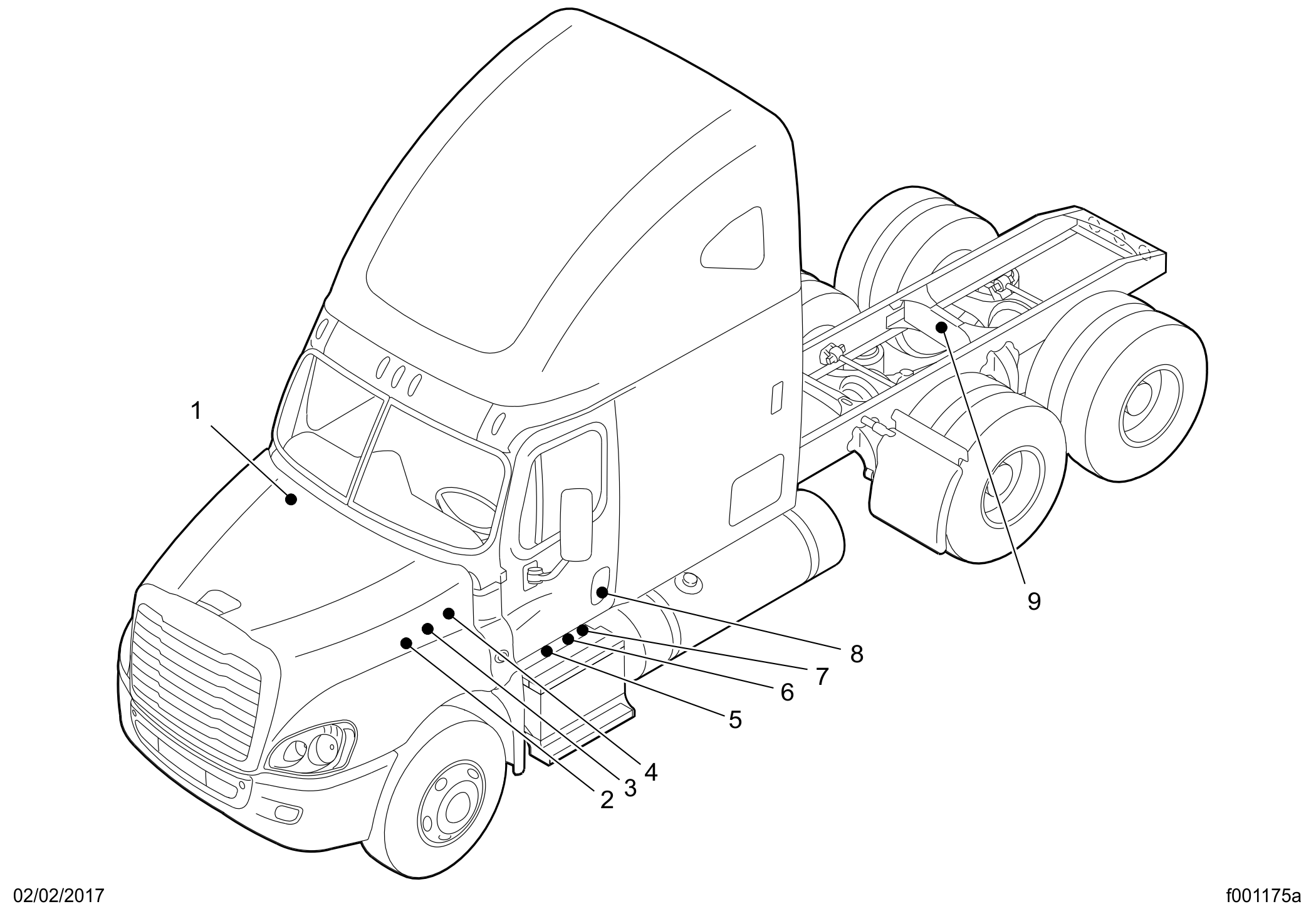
- 1. SAM Cab
- 2. Powertrain PDM (PT-PDM)
- 3. Powernet Distribution Box (PNDB)
- 4. SAM Chassis
- 5. Main Ground Junction Block
- 6. MEGA Fuse Junction Block
- 7. Cab Load Disconnect Switch (optional location)
- 8. Cab Load Disconnect Switch (optional location)
- 9. Trailer PDM
Fig. 3.1, Component Locations
Powernet Distribution Box (PNDB), EPA10 and newer
Cab Load Disconnect Switch
MEGA Fuse Junction Block, EPA07
On EPA07 vehicles, the MFJB distributes battery power to the alternator, SAM cab, SAM chassis, and powertrain PDM. Battery power may also be routed to an inverter and a trailer PDM. The MFJB houses up to five MEGA fuses, and is located on the left frame rail in front of the batteries. See Fig. 3.2 .
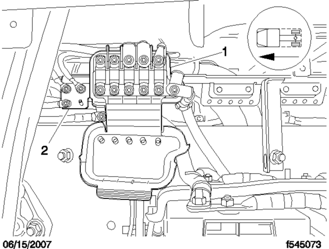
- 1. MEGA Fuse Junction Block
- 2. Main Ground Junction Block
Fig. 3.2, EPA07 MEGA Fuse Junction Block
Powernet Distribution Box, EPA10 and Newer
The PNDB distributes battery power to the SAM cab, SAM chassis, powertrain PDM, and other keep-alive circuits.
The PNDB is mounted in the engine compartment on the frontwall near the steering column. The label on the PNDB fuse cover identifies typical circuits. See Fig. 3.3 .
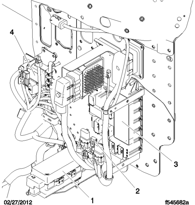
- 1. Powertrain PDM (PT-PDM)
- 2. Inline Fuse, Auxiliary PDM
- 3. SAM Chassis
- 4. Powernet Distribution Box (PNDB)
Fig. 3.3, Engine Compartment Power Distribution Components
Power Distribution Modules
Powertrain PDM
The powertrain PDM contains fuses and relays that provide battery and ignition power to the engine, aftertreatment device, transmission, and other powertrain-related circuits. It is mounted in the engine compartment, above the driver-side inner fender.
Auxiliary PDM
The optional auxiliary PDM is used when additional circuit protection is needed for optional features. For example, if a beacon light is added to the Cascadia, it may require an auxiliary PDM. The auxiliary PDM may contain fuses and relays for these devices. It is mounted in the cab, behind the doghouse cover.
Trailer PDM
The optional trailer PDM, mounted on the frame rail, is used to supply trailer power to the chassis-mounted trailer receptacles. The SAM chassis supplies control signals to the relays in the trailer PDM.
SAM Cab
The SAM cab is located behind the glove box inside the vehicle cab. See Fig. 3.4 . The SAM cab contains fuses and relays in addition to solid state circuit protection devices that will trip when a circuit is overloaded.
Refer to Chapter 25 for fuse and relay locations.
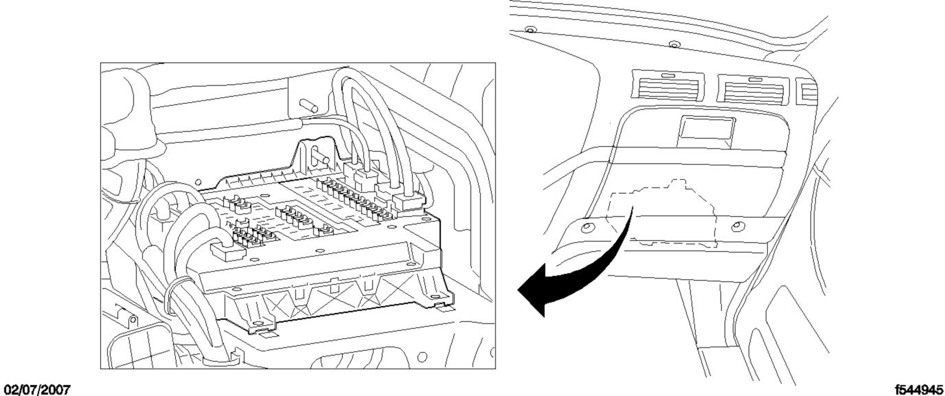
Fig. 3.4, SAM Cab Location
SAM Chassis
The SAM Chassis is located in the engine compartment on the driver-side frontwall. See Fig. 3.3 . The SAM chassis contains fuses and relays in addition to solid state circuit protection devices that will trip when a circuit is overloaded.
Refer to Chapter 25 for fuse and relay locations.
Circuit Protection Features
The SAM chassis and SAM cab may be equipped with self-resetting circuit breakers instead of fuses. Self-resetting circuit breakers are tripped when they reach 170°F (77°C), then self-reset once the temperature drops sufficiently. When the circuit overload is removed, this circuit protection will self-reset. Some of these circuits require the ignition switch to be cycled off then back on again for the self-reset to occur.
Some ECU's are equipped with a self-resetting circuit breaker removal tool.
Always wear heat-protective gloves when handling a self-resetting circuit breakers, which can reach extremely high temperatures. Failure to use appropriate heat protection can lead to serious injury.
Self-resetting circuit breakers can be permanently damaged if improperly handled. Use the guidelines below to handle them safely.
Disconnect the batteries before removing a self-resetting circuit breaker.
Use a circuit breaker removal tool to remove a self-resetting circuit breaker. See Fig. 3.5 . Use of any other tool, including pliers, may damage the circuit breaker.
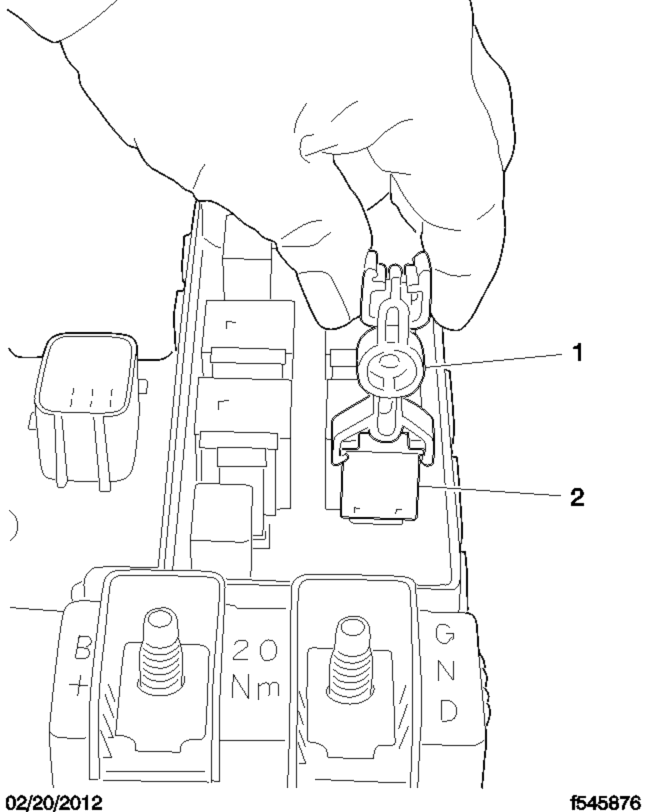
- 1. Circuit Breaker Removal Tool
- 2. Self-Resetting Circuit Breaker
Fig. 3.5, Self-Resetting Circuit Breaker Removal
Never attempt to probe a self-resetting circuit breaker while installed on the SAM Cab or SAM Chassis. Remove the circuit breaker first, or use a non-contact infrared thermometer to measure temperature.
Cab Load Disconnect Switch
Turning the cab load disconnect switch (CLDS) to the off position does not disconnect the connection between the battery and the starter. To work on the vehicle safely, the negative leads must be disconnected from the battery.
IMPORTANT: The ignition should be turned off before turning the CLDS to on or off.
The CLDS is used to avoid excessive draw on the battery when the vehicle is parked for an extended period of time by disconnecting (or opening) the connection between the battery and the most of the vehicle electrical system.
The CLDS may be mounted:
inside the cab on the outboard side of the driver's seat;
outboard on the left frame rail.
See Fig. 3.6 for an EPA07 CLDS; see Fig. 3.7 for an EPA10 and newer switch.
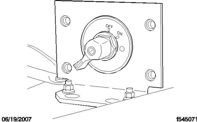
Fig. 3.6, Cab Load Disconnect Switch, EPA07
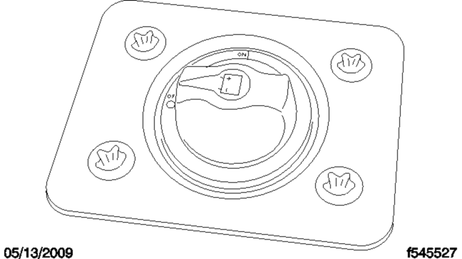
Fig. 3.7, Cab Load Disconnect Switch, EPA10 and Newer
If the CLDS is turned to the off position while the vehicle is running, the emergency power system will activate. The powertrain PDM will receive power from the emergency power feed, but the batteries will not be charging. See the Emergency Power Supply heading below for details.
Where Is the Fuse Box on a 2017 Freightliner Cascadia
Source: https://dtnacontent-dtna.prd.freightliner.com/content/public/dtna-servicelit/dtna/en_us/freightliner/drivers-manuals/cascadia-drivers-manual/section_ch03dm478/subject_ch03dm478_0.html
0 Response to "Where Is the Fuse Box on a 2017 Freightliner Cascadia"
Post a Comment